APPLE PARING AND SLICING MACHINE
A worm-shaft carries the knives past the apple, then a weight drags them home
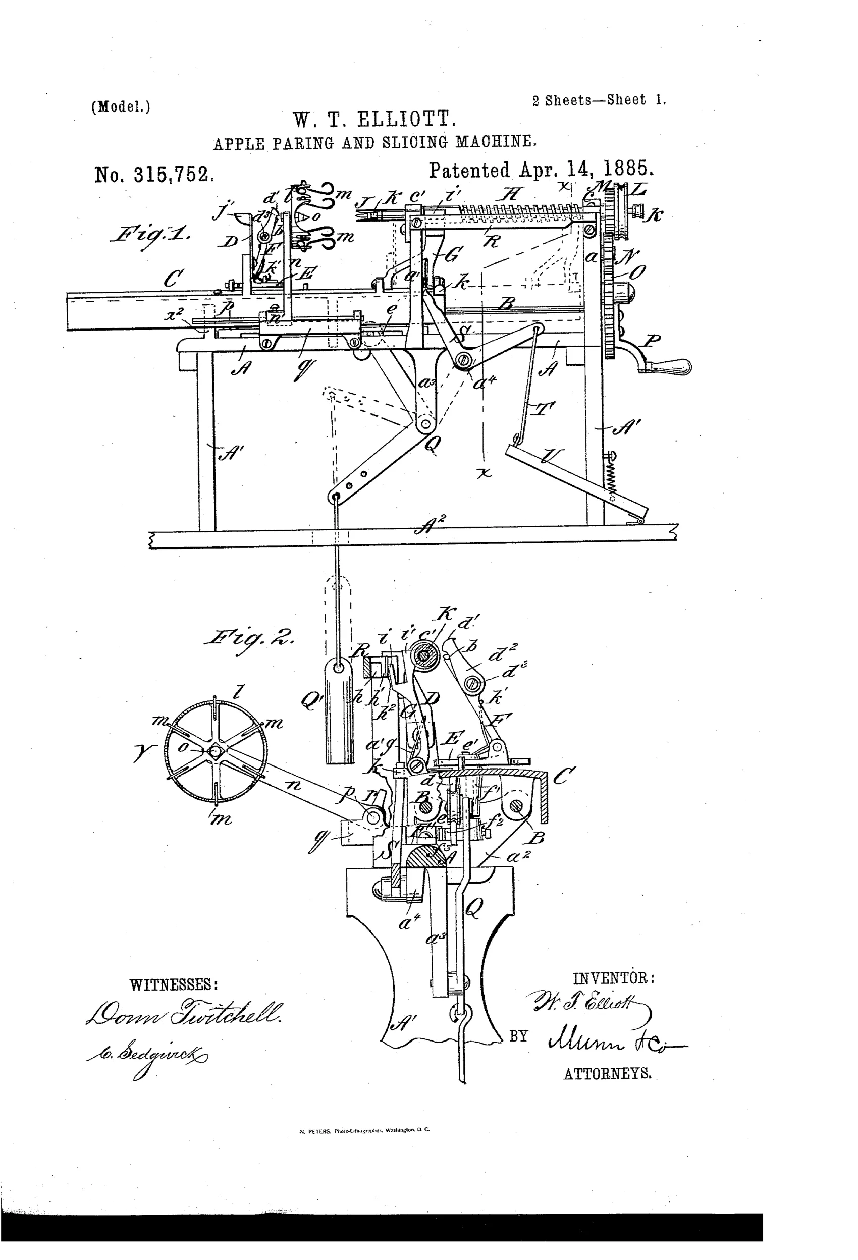
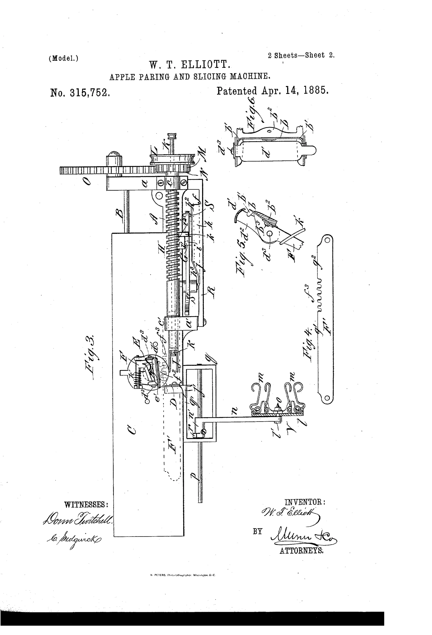
Machine for coring, paring, and slicing apples
❧ How it works
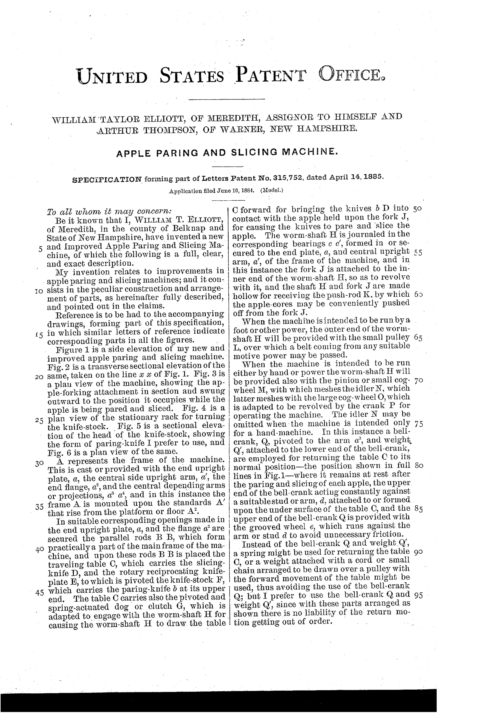
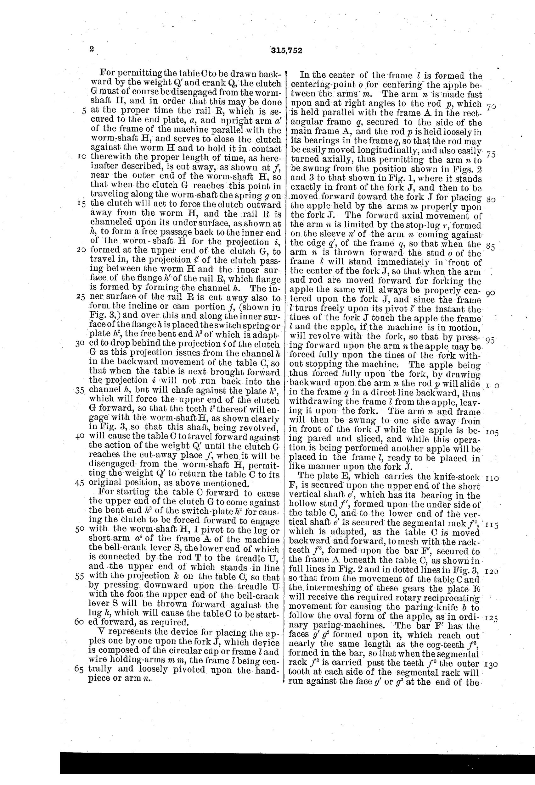
A rotating fork mounted on a worm-shaft holds and spins the apple while a sliding table carrying a paring knife and a rotary slicing knife travels along parallel rods to pare and slice it. A clutch on the table engages the worm-shaft, driven by hand crank and gearing, to draw the table forward past the apple; a switch-plate and cut-away section on a guide rail disengage the clutch after slicing, allowing a weighted bell-crank to return the table to its start position. A segmental rack and stationary rack-bar rotate the knife-stock plate so the curved paring knife follows the oval contour of the apple, and a hollow push-rod through the fork ejects the core. A separate pivoted cup-and-fork loading device centers and presents each apple onto the fork without stopping the machine.
❧ What was claimed
“The rail R, provided with the bent switch-plate h^2, and cut away at f, in combination with the worm-shaft H, carrying the fork, and sliding knife-carrying table C, provided with the clutch G, arranged substantially as and for the purposes set forth.”
In plain English: A guide rail with a cut-away section and spring switch-plate works together with the rotating fork shaft and sliding knife table's clutch to automatically engage and disengage the table's forward drive during paring.
❧ In the inventor’s words
“The apple being thus forced fully upon the fork, by drawing backward upon the arm n the rod p will slide in the frame q in a direct line backward, thus withdrawing the frame l from the apple, leaving it upon the fork.”— William Taylor Elliott, from the specification
Fate unknown
No production machine matching this design is documented in the collector literature (DATAMP included); a marked surviving example would settle it.
❧ Commentary
Most parers of the 1880s spin the apple and swing the blade around it on a gear-driven arm. Elliott inverts the usual proportions: the apple just sits and spins on its fork while an entire sliding table — paring knife, rotary slicing knife, and all — clutches onto a worm-shaft and gets screwed forward past the fruit. When the cut is done, a cut-away section in the guide rail kicks the clutch loose and a weighted bell-crank (that pendulum hanging below the bench in Fig. 1) hauls the table back to its start. It is a machinist's answer to a kitchen problem, closer to a screw-cutting lathe carriage than to a Reading '78.
The cleverest detail is easy to miss: the segmental rack meshing with a stationary rack-bar rotates the knife-stock as the table travels, so the curved paring blade rolls around the apple's oval profile instead of relying on a spring to chase it. That's a positive, geared answer to the problem every lathe-type parer solved with a flexing arm. Elliott even adds a pivoted wire cup that centers and shoves each apple onto the fork without stopping the crank — he was clearly thinking evaporator-house throughput, not the family sideboard.
But all that iron — clutch, switch-plate, worm-shaft, weighted return — is exactly what kept designs like this on paper while Goodell and Sinclair Scott sold simpler machines by the trainload. A New Hampshire inventor in apple-drying country had the right customer in mind; the cost per unit likely said otherwise.
Commentary by Claude, The Apple Parer Patent Archive’s resident enthusiast