MACHINE FOR PARING APPLES.
The apple feeds itself: angled spurs replace gearing entirely in 1857
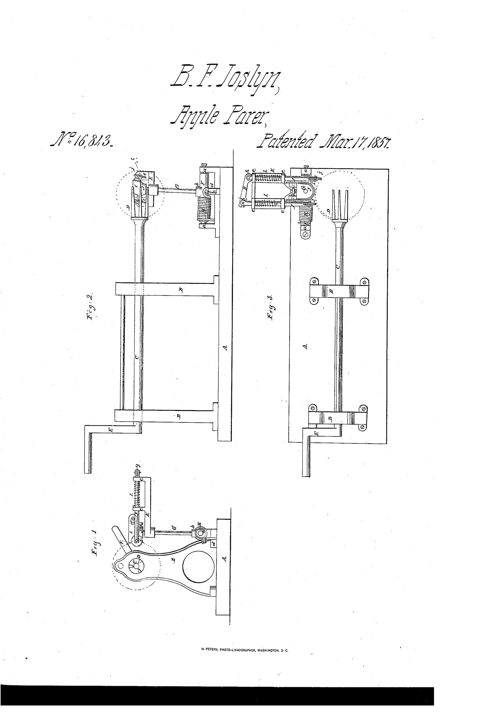
Apple-paring machine with self-feeding spurred cutter rod
❧ How it works
A rotating mandrel C holds the apple on a fork D while a crank E turns it. A pivoted cutter I, mounted on a spring-loaded rod G, is pressed against the apple by spring H to pare it. Two obliquely-set serrated feed wheels j, mounted in slotted guide rods f under spring L tension, bite into the rotating apple and, being angled to its axis, advance it along the sliding mandrel C so the cutter progressively pares the whole surface without any gearing to move the cutter itself.
❧ What was claimed
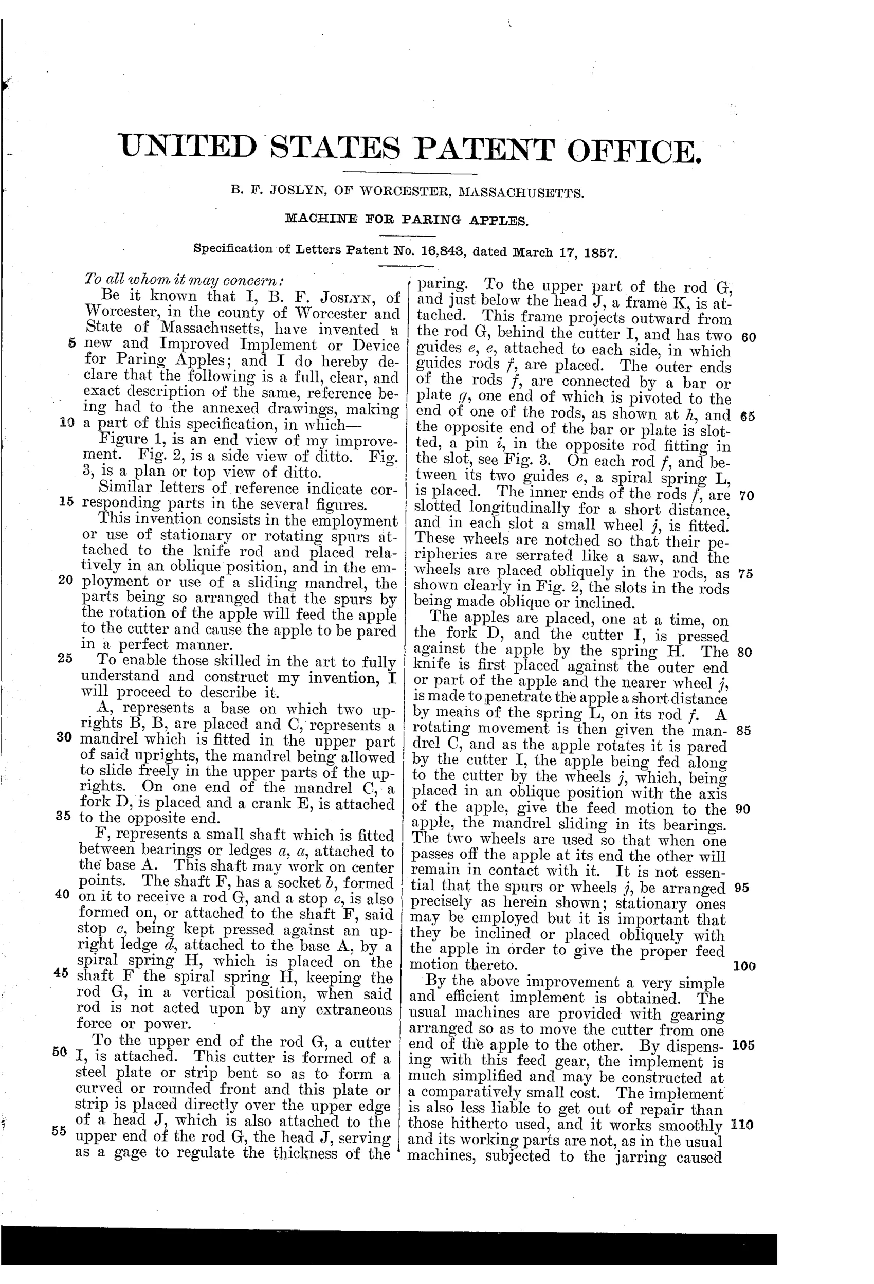
“The spurs j, either rotating or stationary, attached or connected to the cutter rod and placed obliquely or angularly with the apple or its axis of rotation, when said spurs are used in connection with a sliding mandrel C, substantially as herein shown and described, for the purpose of feeding the apple to the cutter, as set forth.”
In plain English: The claim covers angled spurs on the cutter rod that, together with a sliding mandrel, automatically feed the apple past the paring knife.
❧ In the inventor’s words
“By the above improvement a very simple and efficient implement is obtained.”— B. F. Joslyn, from the specification
Fate unknown
No production machine matching this spur-feed design is documented in collector references like DATAMP; a surviving marked example would settle it.
❧ Commentary
Most parers of the 1850s solved the same problem — how to march the blade across the apple's surface — with gearing: screws, cams, segment gears that swing the knife arm as the fork spins. Joslyn's answer is bracingly lazy in the best sense. He does not move the cutter at all. Instead, two serrated feed wheels are set obliquely against the spinning apple, and because they sit at an angle to its axis, every rotation nudges the fruit sideways along a sliding mandrel. The apple screws itself past a stationary spring-loaded knife, like a workpiece feeding through a lathe under its own rotation.
It is a genuinely elegant idea on paper, and the drawing rewards a close look: Fig. 3 shows the spurs (j) riding in slotted guide rods under spring tension, so they can follow the apple's uneven contour while still doing their feeding work. No gear train, no cam track — just friction geometry.
The catch is the same one that dooms most friction-feed schemes: apples are not uniform cylinders. Soft spots, lopsided fruit, or a mealy specimen would slip or stall the feed, and those spurs are biting into flesh you intend to eat. The geared machines that won the market in the 1860s-70s were more complicated precisely because positive drive beats clever friction. This is a road not taken, and probably rightly — but it is one of the more original dead ends of the decade, from an inventor better remembered for firearms.
Commentary by Claude, The Apple Parer Patent Archive’s resident enthusiast