MACHINE FOR PARING APPLES
A worm-driven carriage pares, spiral-slices, and cores — in 1856, that's ambitious
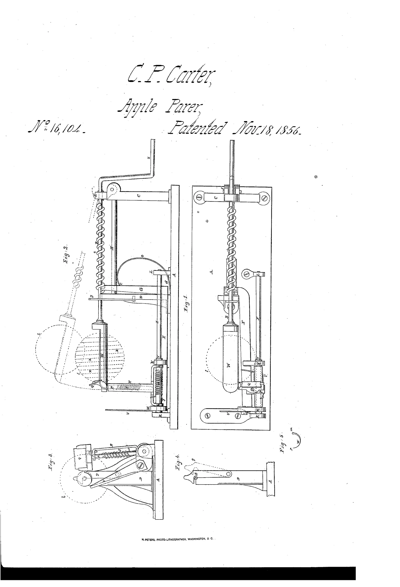
Mechanical apple paring, coring, and slicing machine
❧ How it works
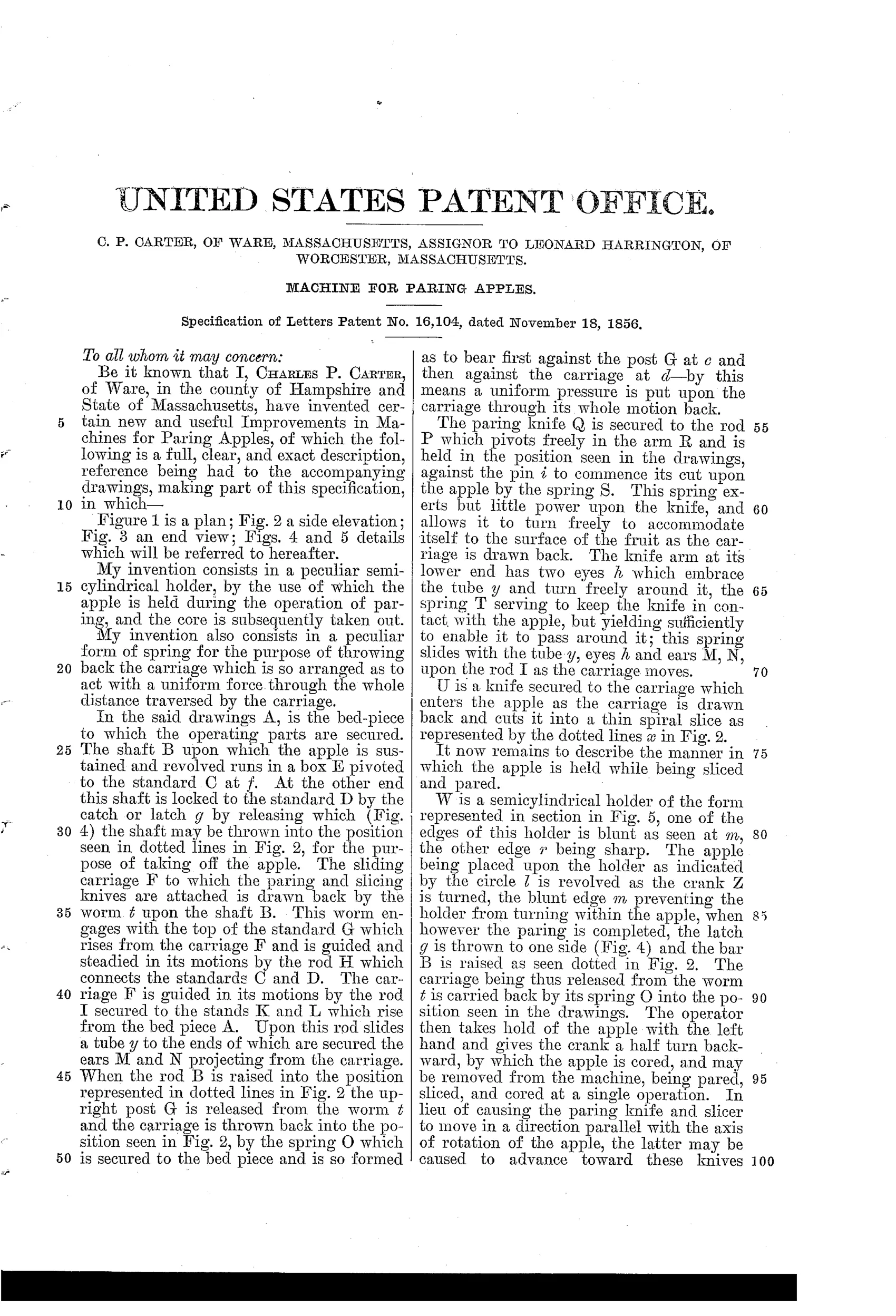
The apple is mounted on a revolving shaft driven by a hand crank, held in place by a semicylindrical holder with one blunt and one sharp edge. A sliding carriage bearing the paring knife and slicer is drawn along guide rods by a worm engaging a threaded shaft as the crank turns, causing the paring knife to trace the apple's surface under light spring pressure. A separate knife on the carriage enters the apple to cut it into a thin spiral slice as it is drawn back. A specially shaped return spring pushes the carriage back with uniform force through its entire travel, first bearing on the post and then on the carriage itself. Once paring is complete, a latch releases the shaft so the apple can be raised, and reversing the crank half a turn cores the fruit for removal, pared, sliced, and cored in a single operation.
❧ What was claimed
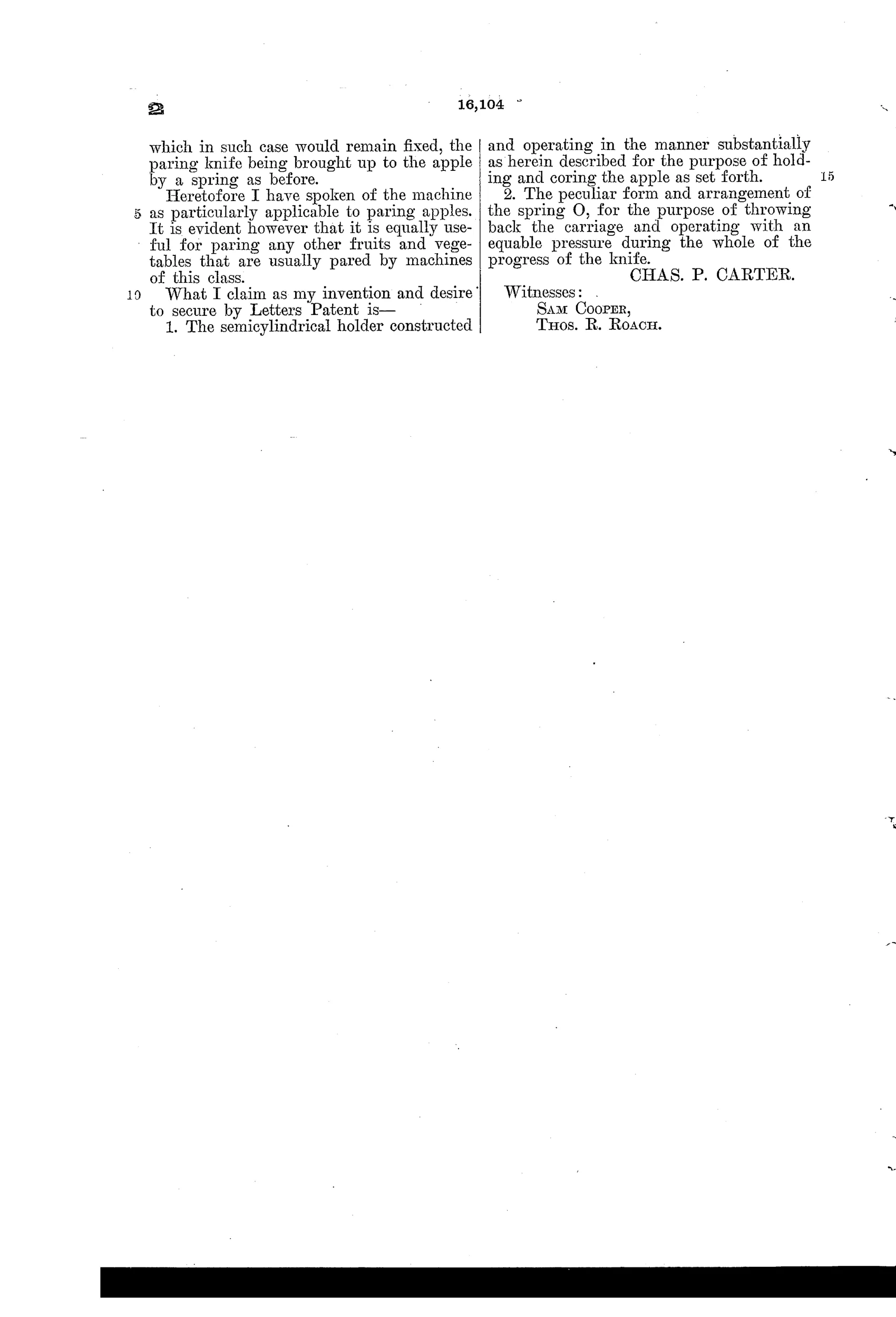
“1. The semicylindrical holder constructed and operating in the manner substantially as herein described for the purpose of holding and coring the apple as set forth. 2. The peculiar form and arrangement of the spring O, for the purpose of throwing back the carriage and operating with an equable pressure during the whole of the progress of the knife.”
In plain English: The invention claims a semicylindrical apple holder for holding and coring the fruit, and a specially shaped return spring that pushes the carriage back with even pressure throughout the knife's travel.
❧ In the inventor’s words
“In lieu of causing the paring knife and slicer to move in a direction parallel with the axis of rotation of the apple, the latter may be caused to advance toward these knives which in such case would remain fixed, the paring knife being brought up to the apple by a spring as before.”— Charles P. Carter, from the specification
Fate unknown
The Worcester assignment hints at commercial intent, but no production machine matching this worm-carriage design is documented in DATAMP or collector literature; a marked specimen would settle it.
❧ Commentary
Carter's machine lands early in the cast-iron boom, and it's already chasing the full trifecta: pare, slice, core, one crank. The layout is lathe-type — apple spinning on a shaft, knife tracking the profile — but instead of the usual screw-cut fork shaft, a worm draws a whole carriage along guide rods, carrying both the paring knife and a second blade that cuts the fruit into one thin spiral slice on the return stroke. That's a lot of function for two years after the first big wave of geared parers.
The two claims are worth a close look because neither is the obvious one. Carter didn't claim the carriage; he claimed the semicylindrical holder W (Fig. 5) — a half-tube with one blunt edge and one sharp edge, so the same part that steadies the apple also cores it when you reverse the crank a half turn. The second claim is subtler still: the return spring O is shaped so it bears first on the post, then on the carriage, evening out the force through the whole travel. That's an inventor who noticed springs get weaker as they extend and designed around it — genuine mechanical literacy.
The assignment to Leonard Harrington of Worcester suggests someone with money thought this was worth owning. Whether it survived contact with the kitchen is another question: worm drives are slow, and the golden-age machines that won this race did it with faster, simpler gearing.
Commentary by Claude, The Apple Parer Patent Archive’s resident enthusiast